2. From Snell’s law to Vergence formula
The vergence formula is beneficial in ophthalmic optics. All paraxial IOL power calculation formulas that use an optical model of the eye are based on the use of the vergence formula, which allows calculating the position where an object’s image is formed after refraction of light by an optical system. This system can be simple (a thin lens) or more complex (cornea + lens).
The vergence formula is also used outside the paraxial domain to convert into dioptric units of topographic curvature information in axial or tangential keratometric mode; it is crucial to understand the differences between the use of this formula in the paraxial domain and outside it.
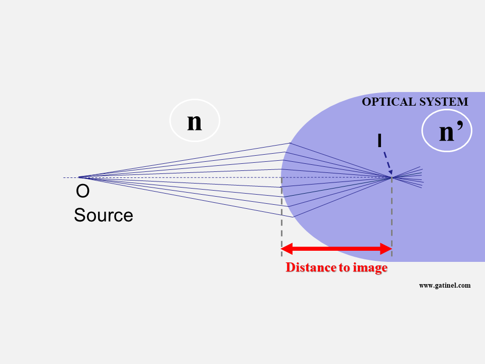
How to compute easily the distance of the image formed by the optical system?
Using the vergence formula allows various calculations to be made without calculating the path of many rays through the paraxial region of the optical system. It allows, among other things, to establish a simple formula for calculating the intraocular lens (IOL) power during cataract surgery: this power is computed as the subtraction between vergences. It also allows formulas to be established to convert a spectacle lens’s power from a contact lens power (and vice versa) as a function of the distance between the spectacle plane and the eye.
As we will see later, the vergence formula involves the source object’s position, distance in the incident medium with the optical system, and the vergence or optical power of this system.
Before establishing the formula for vergence, it is necessary to familiarize yourself with the notion of vergence!
What is vergence?
Vergence – analogous to the paraxial optical power – is expressed in diopters (D or δ). For an optical surface, it is equal to the inverse (reciprocal) of the distance to the focus, where the clear image is formed, multiplied by the refractive index of the medium considered.
Let n be the refractive index of the medium considered, and f the distance to the focus:
V = n / f
Vergence corresponds to the ratio between the medium’s refractive index and the distance between the interface considered and the focus.
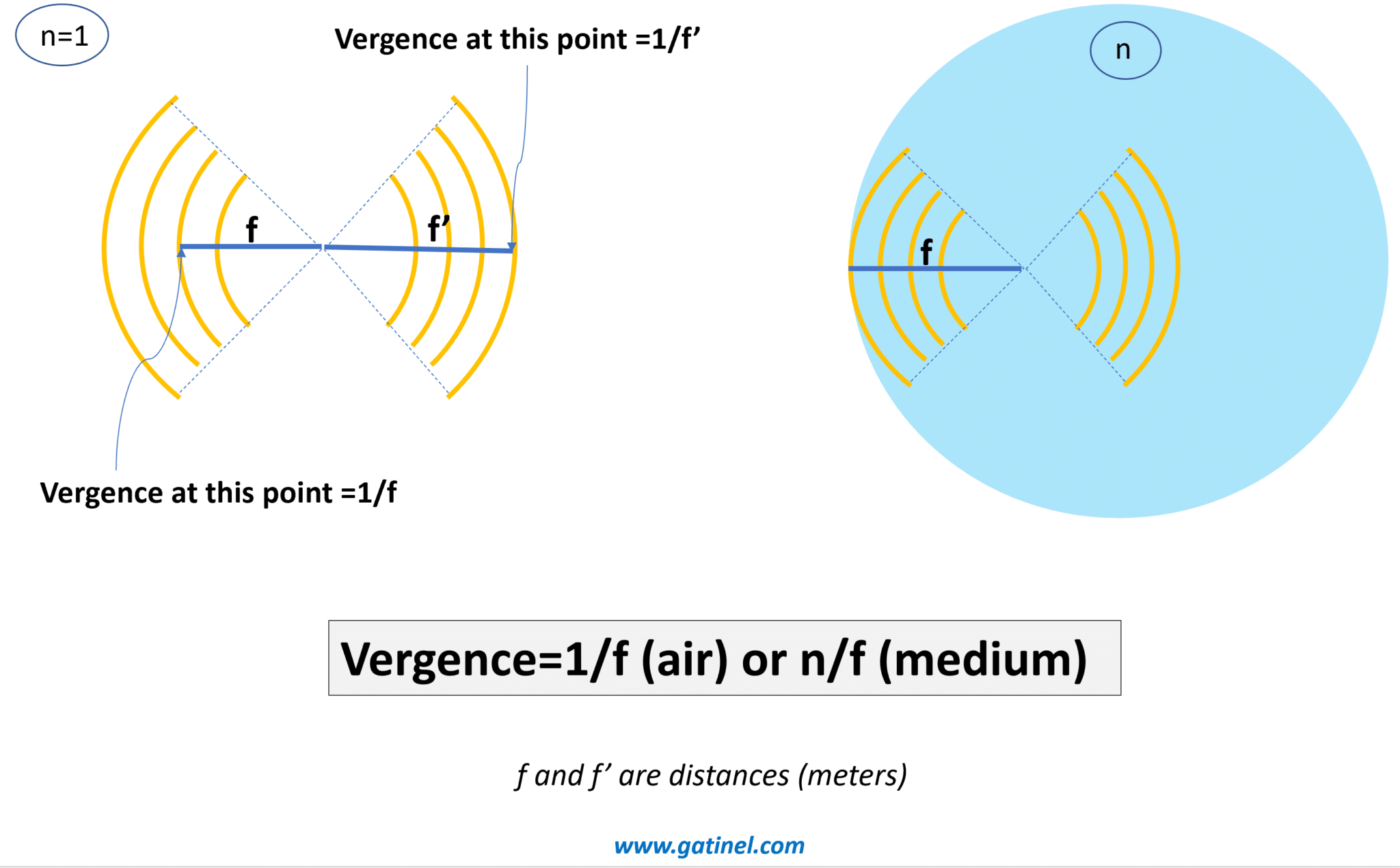
Vergence in air (n=1) or in a medium (n>1)
Vergence is an advantageous quantity for predicting the focal point (s) of an optical system. If we know the vergence at some point, we know the focus’s position from that point, which is equal to the inverse of the vergence divided by the refractive index of the propagation medium. The vergence calculation at a given point does not prejudge the possible presence of other optical elements on the path towards the focus, which remains hypothetical as long as it is not reached. When we approach the notion of vergence, it can be useful to visualize the movement of light information as a succession of spherical envelopes (circular in section), which diverge from -or converge towards – a focus. We then find an analogy with the notion of a wavefront.
A wavefront is a virtual construction: it corresponds to the envelope of points in space in the same phase state whose variations are represented by the wavetrains (sinusoids). A ray is another virtual construct that corresponds to the local direction of movement of the wavefront.
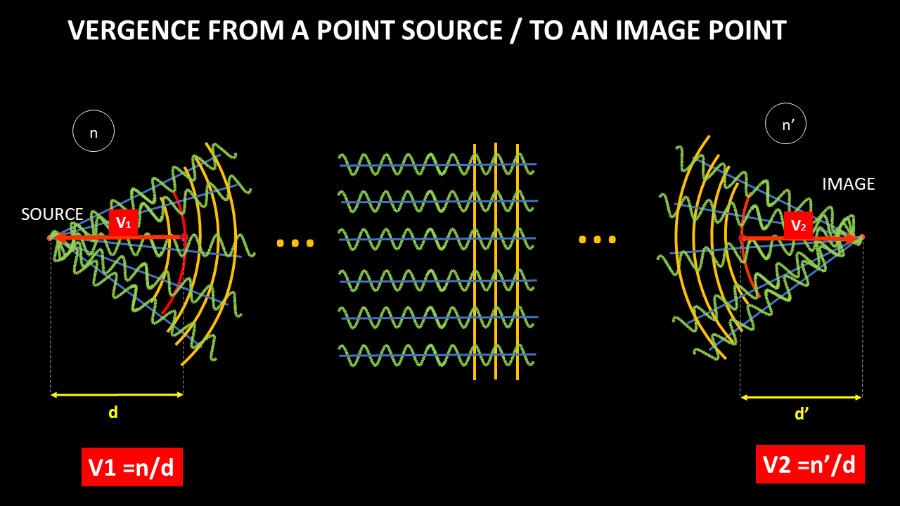
Light emission from a source, propagation to an image formed by an optical system.
In paraxial biometric calculation, we are interested exclusively in refractive correction problems that involve vergence. In Ophthalmology, the notion of a wavefront is more usually linked to that of optical quality. In this context, we are mainly interested in qualifying and quantifying the local deformations of the edges of the wavefront. The vergence can be understood as a magnitude that depends on the distance that separates the envelope of a localized wavefront from the focus from which it seems to have been emitted or from the focus towards which it seems to converge. Therefore, the vergence is related to the paraxial curvature of the wavefront: we can relate the vergence of a wavefront to the low-degree 2 contingent of wavefront aberrations. These considerations do not directly affect what follows, but I hope to allow the reader to relate some basic notions together.
The total vergence of the phakic eye depends on the vergence of the cornea, the crystalline lens, and the distance that separates them. During accommodation, the lens’s vergence increases (the lens deforms and takes on a greater curvature).
Similarly, in the pseudophakic eye, the total vergence depends on the vergence of the cornea, of the IOL, and the distance that separates them.
At this point, it is important to remember that an inverse relationship relates to vergence and distance. Suppose we use a formula for calculating the vergence at a point in space. In that case, we can easily deduce the distance that separates this point from the focus – in the case, of course, where the light continues its path in the same propagation medium.
When we talk about the value of a vergence (which is expressed in diopters), we must keep in mind that this notion depends on the precise location where we consider this vergence. In the above, the total vergence of the cornea + lens/IOL duo refers to the position immediately following the lens (or IOL). Suppose the total vergence of the eye is equal to, say, 65 D. In that case, we can deduce that the wavefront emerging from the lens will focus at the distance of 1.336 / 60 = 0.02055 mm = 20.55 mm from the lens, where 1.336 is the value of the index refraction of the vitreous, since it is in this medium that the wavefront propagates after crossing the cornea and the lens.
Example: predicting the refraction of an aphakic eye using the properties of vergence.
An aphakic eye (without lens) is a refracting system comprising a single optical lens: the cornea. The medium for the propagation of light after refraction by the cornea is the vitreous (n = 1.336).
The biometer provides the measurement of the keratometry (estimate of the paraxial optical power of the cornea), which is equal to 42.71 D.
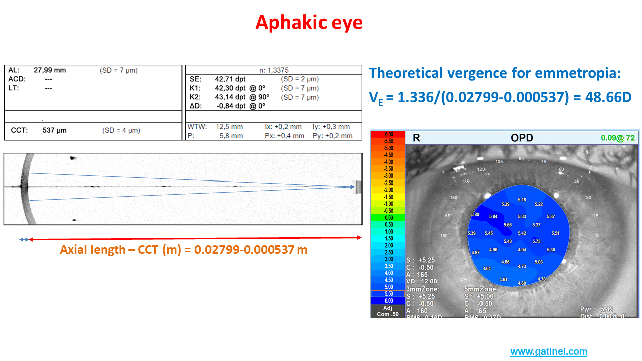
Biometry, keratometry and refraction of an aphakic eye.
Let us now calculate the theoretical vergence necessary for the light rays to be refracted in the retinal plane after refraction by the cornea. The distance between the posterior surface of the cornea and the retina is equal to the subtraction between the axial length and the central corneal thickness (0.02799 – 0.000537 in meters). The vergence is equal to the ratio between the refractive index of the vitreous and this distance expressed in meters, namely: 1.336/(0.02799 – 0.00537)=48.66D
The difference between the corneal vergence and the theoretical vergence of the emmetropic aphakic eye is equal to 48.66 – 42.71 =5.95 D. An aberrometry measurement (OPDscan III) provides an estimate of the refraction at +5.50 D … in the spectacle plane, which corresponds well to hyperopic refraction of about +6 D in the corneal plane.
The rest of this page is mostly devoted to the vergence formula: its origin is reported, and a few applications are mentioned.
Origin of the vergence formula
The formula for vergence derives from the use of Snell’s (or Snell-Descartes) law (with reference to the scientists Snellius and Descartes) applied in paraxial conditions. It derives from approximations if we consider the small region of the optical system close to the optical axis (paraxial conditions) and where the rays form a small angle with this axis. The vergence formula allows you to calculate the position of a source’s image without needing to use Snell’s Descartes’ formula for all rays (ray tracing), which is tedious and requires the use of dedicated computer software.
When the light source is placed “at infinity,” the distance between the diopter’s apex and the formed image is the focal length (F).
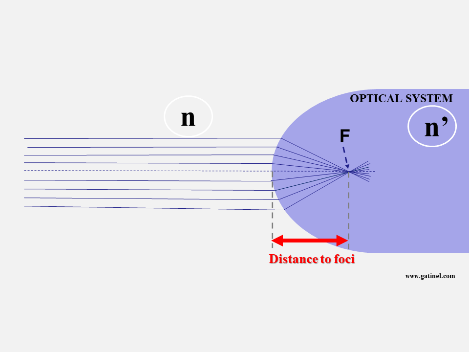
Consider a general case, where the source is located not at infinity but at a distance O and is surrounded by a medium of refractive index n. The optical system is a spherical diopter with radius R and index n’. We know n, n’, O (the distance from the source to the diopter), and R, the radius of curvature of the diopter’s apex.
When the light source is closer than infinity, the image of the source shifts beyond F. To compute this distance, all we need is a simple formula, named the vergence formula, which derives from a few approximations (inset box), linked to the small magnitude of h (height of the incident ray to the optical axis). The vergence formula is therefore only valid for points located close to the axis (paraxial conditions).
R represents the diopter’s radius of curvature (if the diopter is perfectly spherical) or its apical radius (if it is not perfectly spherical). Knowing R is necessary if our formula is to be applied to points near the optical axis. R is close to 8 mm in the cornea, and paraxial conditions apply for points within the central 1mm. Still, they can be extended with reasonable loss of accuracy to the central 3 mm zone, at least in normal situations.
Paraxial approximation conditions in a diopter
Establishing the vergence formula
(The reader with little geometry enthusiasm may skip most of this paragraph and jump to the end of it)
The vergence formula derives from Snell’s law, which allows us to write: n sin θi = n ’sin θr
Under paraxial conditions, we can replace sin θi with the value θi in radians. The equation, therefore, becomes:
n θi = n’ θr
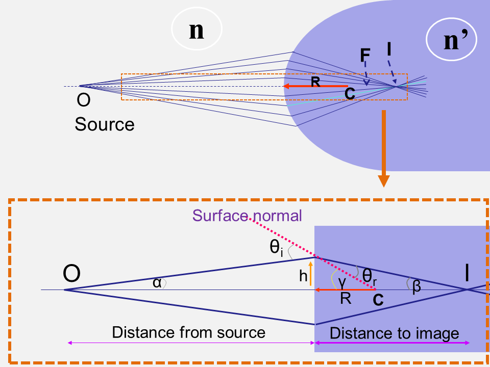
We must now express θi and sin θt as a function of variables that are easier to measure: (remember that we know the position of O, the value of R, n, and n ’).
By observing the figure above, we can put: θi = α + γ
The following figure makes it possible to express the angle of incidence θi as the sum of the ray angle with the optical axis α and the angle between the segment connecting the entry point and the center of curvature and the optical axis γ.
Likewise, it is possible to verify that θr = γ – β
We can then replace θi = α + γ and θr = γ – β in Snell’s law to obtain:
n (α + γ) = n’(γ – β)
n α + n γ = n’γ – n’ β
n α + n ’β = γ (n’ – n)
We can express the angles α γ and β as a function of h, O (distance from the source point to the optical vertex), i, and R (remember that we know the values O and R).
Under paraxial conditions (for small angles):
tan α ≈ α = h / -O = – h / O (the distance O is negative by convention; the distance is measured to the left)
tan γ ≈ γ = h / R
tan β ≈ β = h / I
At this stage, it would suffice to know h to find the value of I. Unfortunately, we do not know this value. However, if we replace the values of the angles with these ratios in the expression:
n α + n’β = γ (n’ – n)
We obtain :
-n h / O + n’ h / I = h (n’ – n) / R
We can simplify the formula by h, and we finally get:
-n / O + n’/ I = (n’ – n) / R
Rearranging terms, we obtain the vergence formula:
n’/ I = n / O + (n’ – n) / R
We can then calculate I since we have « got rid » of the unknowns: the angles and the height of incidence h!
The formula of vergence is aptly named since all its terms correspond to a vergence (or a ratio between a refractive index difference and a distance):
n’/ I is the vergence of (to) the image Vi
n / O is the vergence of (from) the object Vo
(n’ – n) / R is referred to as the paraxial optical power P of the diopter. When the vergence of the object is zero (the object is located at an infinite distance), the vergence of the image is equal to the expression of the power of the diopter. The distance d, which separates the top of the dioptre from the focus, is equal to the ratio between the refractive index of the dioptre and the vergence of the dioptre. We thus obtain d = nR / (n’-n ). The shorter R, the larger the difference in the refractive indices, and the shorter d.
It is important to note that what we call the paraxial optical power of the diopter depends both on the respective refractive index of the adjacent medium and of the diopter and on the radius of curvature of the apex (apical radius) of the diopter.
We can thus write the vergence formula as:
Vo + P = Vi
When we have determined Vi, we know the distance which separates the top of the dioptre from the focus: it is equal to n ‘/ Vi.
Using the vergence formula
We appreciate this formula’s power, which only requires knowing the distance O of the source object with the diopter (of which we know the curvature R and the index n’) to calculate the image’s distance.
To calculate these vergences, it is necessary to consider the sign of the distances: negative to the left (diverging light), positive to the right (converging light). Hence, O<0.
The inverse of a distance (in meters) is expressed in diopters (remember that n and n ‘are dimensionless because they correspond to the ratio between the wavelength in the media, which is equal to the ratio between the speed of light in a vacuum and the speed of light in the media).
For example, if the diopter has an index of 1.37 and a radius of curvature R of 8 mm, the diopter’s vergence in the air is equal to (1.33 – 1) / 0.008 or 41.25 diopters. These are values close to those used to model the paraxial properties of the anterior surface of the cornea.
The vergence formula can be applied to study the vergence in the eye, i.e., propagating an incident light beam through ocular media.
Using the vergence formula applied to a double « cornea + crystalline » system, we can establish a paraxial formula for calculating IOL power.
Outside paraxial conditions
The vergence formula is based on a paraxial approximation and cannot be applied at a distance from the optical axis to predict the focal length of an incident beam. As we will see later, the vergence formula is, however, used for the representation of corneal curvature in dioptric units.
We will show that spherical optics (circular in section) are not stigmatic, apart from paraxial conditions. Even if this apparently takes us away from our main topic, it is useful to forge links to asphericity concepts and introduce some fundamental notions useful in cataract surgery and refractive surgery.
To begin with, we will recall some useful equations concerning the profile of a circular section. It suffices to remember the Pythagorean theorem to establish the equation of a circle centered on the origin of a Cartesian coordinate system. However, when a circle describes the curvature of an optical surface, it is shifted so that the origin of the Cartesian coordinate system coincides with the vertex of the circle. We can easily establish the equation of the shifted circle.
The following figure represents the geometric elements involved in the case of refraction by a circular surface in section:
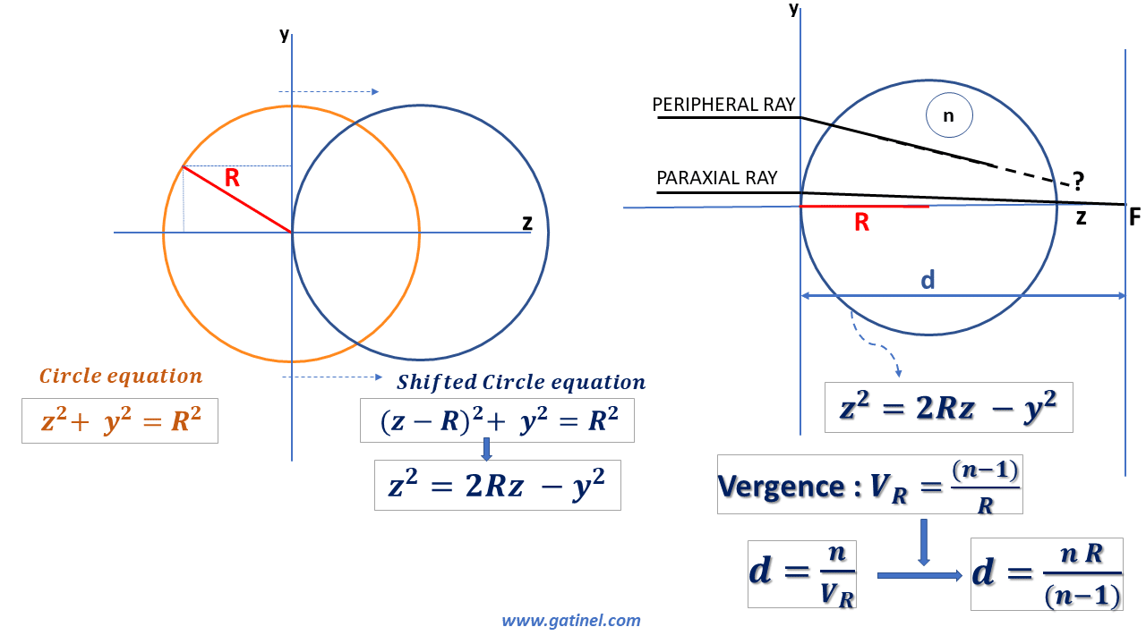
If we consider this profile a circular diopter of refractive index n, we can determine its vergence and focal length in paraxial conditions.
But what happens for a more peripheral ray?
To answer this question, we can establish the conditions for a diopter to be perfectly stigmatic for a source located at infinity; it suffices for the optical path, a notion that we have discussed previously, to be identical for any incident ray coming from a distant source (it is assumed here that the rays propagate in the same medium after having encountered the spherical diopter). For a given wavelength, the optical path is a concept specific to wave optics; it is equal to the physical distance multiplied by the refractive index of the propagation medium (the refractive index is the ratio between the wavelength considered in a vacuum and the wavelength considered in the medium; the index is an eigenvalue at a specific wavelength). The frequency of light waves is unchanged regardless of the medium, but the speed of propagation decreases with its density, which causes a shortening of the wavelength.
If the optical path length from the source to the image is the same for all refracted rays, perfect stigmatism will occur. Intuitively, it is conceivable that the rays located near the vertex represent an optical path where the path in the air is shorter than that of the more peripheral rays, which meet the surface of the diopter a little further. These rays take a certain lead, which will have to be compensated for at the path level in the medium of the diopter.
The following figure is a little busy, but it allows us to establish with certainty that the equation of the profile of a perfectly stigmatic surface is not that of a circle, but an aspherical curve:
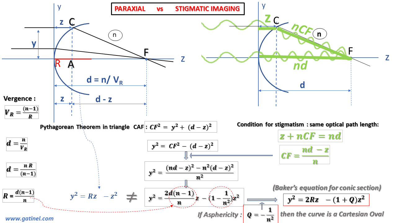
We can establish the equation that satisfies this condition of stigmatism and the equality between the optical paths for a ray coincident with the optical axis and a peripheral (non-paraxial) ray coming from a distant source. Using the geometry of the figure and the Pythagorean theorem, we can establish an equation that includes our useful parameters: the radius of curvature of the diopter R, its refractive index n, and the coordinates of the Cartesian system (y,z).
By identifying the equation describing the profile of a perfectly stigmatic diopter with that of a circle, we realize that there appears a difference with the equation of the circle. The factor weighting the term in z^2 contains a constant (usually named Q), which characterizes the asphericity (literally the « defect or absence of sphericity »). The equation thus rearranged corresponds to the « Baker’s equation » (see the figure above) and describes, when Q = -1 / n^2, the profile of a perfectly stigmatic optic, often referred to as « Cartesian oval. »
This Cartesian oval is comparable to the tip of a negative ellipse whose value of the factor Q is negative and between 0 and -1. This elliptical tip of negative asphericity is qualified as prolate: its local curvature decreases from the vertex to the periphery, until the other vertex of the ellipse, which is qualified as oblate and whose Q factor is positive. Ellipses are part, with the circle, the parabola, and the hyperbola, of a family of curves, called conic sections (as this name suggests, the section of the sheet of a cone by a plane can generate one of these curves as a function of the plane’s cutting angle).
The corneal profile is slightly aspherical and conveniently modeled by a conical section using two parameters: the apical or « osculating » radius (R) and the asphericity parameter Q. Baker’s equation is convenient because it is established from these two parameters of clinical importance: R, which governs the paraxial properties (and must therefore be considered for calculations using the vergence formula) and Q, which governs the non-paraxial properties.
The following diagram gathers the equations and terms useful for studying the conical sections applied to the corneal profile. The prolate vertex (or tip) of the ellipse has a curvature that decreases from the center O towards the periphery (up to the oblate tip).
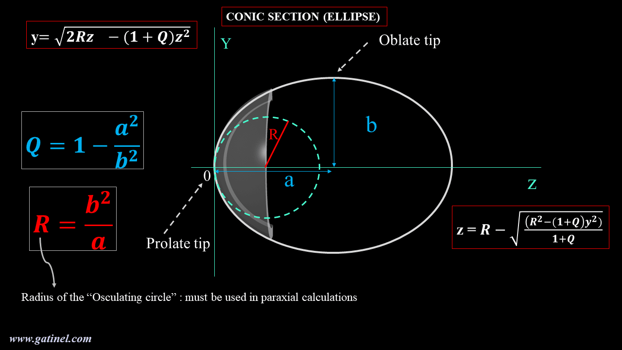
As stated before, for paraxial calculations intended to estimate the optical power of the cornea, we must use the radius of curvature of the osculating circle at the corneal vertex (R in the above figure). In practice, it is provided by the keratometric measurement (in mm, or in diopters after a conversion that can use a reduced refractive index, or a paraxial calculation that takes into account the posterior face of the cornea). In practice, near the apex, the profile of the osculating circle and that of the perfectly stigmatic aspherical corneal surface can be confounded.
The refractive index of the corneal stroma is equal to 1.376. The theoretical value of the corneal asphericity, which would make the corneal diopter a perfectly stigmatic surface (i.e., a Cartesian oval), is equal to Q = -0.528. The average asphericity of the profile of the human cornea is measured close to Q = -0.25; it is slightly less « prolate. » Even if the radius of curvature decreases at the periphery (moderate prolateness), this reduction is not large enough to counter the increase in the angle of incidence of the peripheral rays coming from distant sources. In terms of power, the optical power of the anterior surface of the human cornea increases slightly physiologically towards the periphery. Even if the radius of curvature decreases at the periphery, this reduction is not large enough to counter the increase in the angle of incidence of the peripheral rays coming from distant sources.
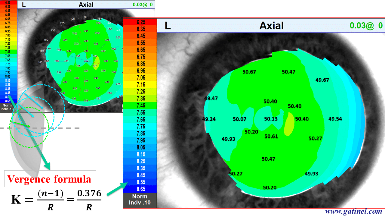
An obstacle to the correct interpretation of corneal topography maps is linked to a historical element deriving from the representation of the axial curvature in units called « keratometric power. » It corresponds to the use outside paraxial conditions of the vergence formula.
Axial curvature maps vs. Refractive maps
The corneal topography suffers from unfortunate confusion. While the first algorithms resulting from the collection of a specular image were designed for the calculation of the local radius of curvature in millimeters (in an axial/sagittal or tangential/instantaneous direction), the desire for a representation in a dioptric unit led using the vergence formula to convert the millimeter values from the measurement of the local radius of curvature into diopters.
For the conversion into a dioptric unit, a reduced refractive index value (generally close to 1.335 according to topographers and keratometers and called « keratometric index« ) for the refractive index of the corneal stroma (n = 1.376) was used to compensate for the lack of measurement of the posterior curvature. Indeed, the optical power (the vergence) of the posterior face of the cornea is negative (because the refractive index of the aqueous humor is lower than that of the corneal stroma). As a result, the optical power (vergence) of the total cornea is slightly lower than that of the anterior surface of the cornea alone. This generalized conversion to diopter by using the vergence formula is unfortunately outside of paraxial conditions. It misleadingly suggests that the local optical power of the cornea is being measured. If we really want to study the optical power of the anterior face of the cornea, we must analyze the so-called « refractive » power map of the cornea, which is obtained by using the Snell-Descartes law for a beam of incident parallel rays.
This topographic map, called axial curvature, was obtained using the vergence formula from local curvature data (in mm) and a refractive index equal to 1.376 (refractive index of the stroma). We will then compare this representation with the refractive power map (calculated using Snell’s law and the same refractive index value for the corneal stroma).
The same corneal surface is analyzed using the so-called « refractive power » map, which is calculated using Snell’s law for a beam of parallel incident rays. There is a similarity to the « axial keratometric power » figures at the paraxial region, but a marked difference as one moves away from that central region.
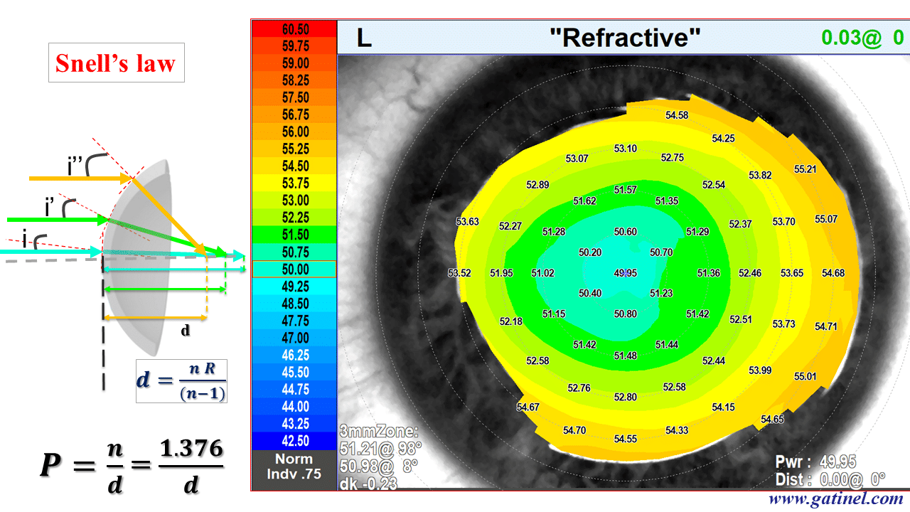
So-called keratometric power should not be confused with real optical power outside the paraxial region!
The extension of the use of Snell’s law to the whole eye makes it possible to perform a biometric calculation by the technique of ray-tracing. It requires the use of dedicated software. In principle, the use of the ray-tracing technique limited to paraxial rays provides a result very close to that obtained by the iterative use of the vergence formula. We will use the latter to characterize the path of the paraxial rays in a pseudophakic eye.