Trifocal IOL – Cataract implant
The development of trifocal intraocular lenses (IOLs) has revolutionized cataract surgery by enabling patients to achieve clear vision at near, intermediate, and far distances without the need for additional corrective lenses. For more than 10 years, trifocal implants have been the most commonly used intraocular lenses when one of the key goals of cataract surgery is to minimize dependence on corrective glasses. This allows the patient to enjoy clear vision without glasses for distance, near (reading), and intermediate distances (working on a computer). This segment of so-called « presbyopia-correcting » lenses accounts for approximately 11% of the total intraocular lens market for cataract surgery. Trifocal implants make up half of this market in Europe (see clinical trends, ESCRS). This page is dedicated to the technical aspects of pioneering trifocal diffractive IOLs.
History of Trifocal IOLs
I played a pioneering role in this development, driven by the lack of intermediate vision in patients implanted with bifocal lenses in the mid-2000s. As a cataract surgeon, I had been using bifocal lenses in patients seeking some spectacle independance during the years 2005- 2007. These patients would often come back to me satisfied with their distance and near vision, but asking for some « screen reading glasses », as they could not really work on their computer, which distance was about 70 cm from their eyes. This was seminal to the project of developing a multifocal IOL which would provide the patients with distance, near AND intermediate vision.
As early as 2007, I began research in collaboration with the research and development team of the Physiol laboratory in Liège, Belgium, headed by Christophe Pagnoulle with whom I had already worked on determining the optimal asphericity of the manufacturer’s soft monofocal lenses. By utilizing optimized diffraction principles, we developed a design that is both simple and elegant, which has since become the standard.
In 2010, the company Physiol (Belgium) then released the first ever designed trifocal intra-ocular lens (IOL) for the replacement of the crystalline lens during cataract surgery. This new generation of multifocal IOL is based on a proprietary diffractive profile and is named « FineVision. » Fine stands for an acronym for « Far, Intermediate and NEar ». This IOL has been implanted in thousands of eyes and produces satisfying and predictable visual performances by allowing the patient to become spectacle-free for near, distant, AND intermediate vision, in comparison to previous multifocal IOLs that were bifocal and did not allow satisfactory intermediate vision.
Watch :Video recorded at Fyodorov Institute, Moscow, on October 27th, 2012. It depicts the fundamental principles of diffractive IOLs and the concepts that presided to the development of this first and new trifocal IOL design:
Read; The Best of Ophthalmology…Testing a Trifocal IOL .EyeWorld News Magazine
Justification of the trifocality
Bifocal diffractive IOLs allow operated patients to some spectacle independence for distant (more than 2 meters) and near (between 35 and 40 cm) vision. These lenses have however not been shown to provide satisfactory intermediate vision.
Intermediate vision relates to activities such as computer work, car driving (instrument panel), music playing (musical chart), etc. In these activities for which good uncorrected vision is required for distances comprised between 60 and 80 cm) glasses may be required despite satisfactory near and distance uncorrected vision. Interestingly, the commercial release of the FineVision IOL was concomittent to the introduction of the iPad in the USA (march 10). Tablets are way heavier than books, and readers usually hold them on their laps, which increases the reading distance to the intermediate vision range (60 – 70 cm).
The benefit of trifocal vs bifocal IOL technology helps patient to better recover a full distance useful spectacle free vision.

Readers in an airport lounge in Los Angles. The need for uncorrected intermediate vision is probably not specific to laptops and tablets screens, but it has increased tremendously since computer age. The distance from the eyes of the readers to the screen falls between 60 to 80 cm in most cases.
This was seminal to the pioneering solution represented by design and introduction of the first trifocal diffractive lens (FINEvision). This lens aims to be more than a bifocal, providing distance and near correction only. The FINEvision lens has an additional foci for intermediate vision, to provide treated patients with a full range of correction : hence, it is a true trifocal IOL (The » FINEvision » commercial designation stands for an acronym: Far – Intermediate-NEar Vision).
The following video relates to the reasons and steps incurred for the development of a trifocal IOL:

This video depicts some of the fundamentals for diffractive IOL design:
Designing a trifocal diffractive IOL
The IOL theoretical profile was first designed from theoretical computational equations. Its effect on an incident wavefront was simulated with MathCAD software (PTC Inc., Needham, Massachusetts, USA). The original idea was to combine two independent diffractive bifocal profiles, yielding a single diffractive pattern (this concept was patented in 2010).
From a Fresnel lighthouse lens to a diffractive optic
Augustin Fresnel was a French scientist from the 19th century, who first developed a concept named after him, the « Fresnel optic », for the lighthouse lamps.
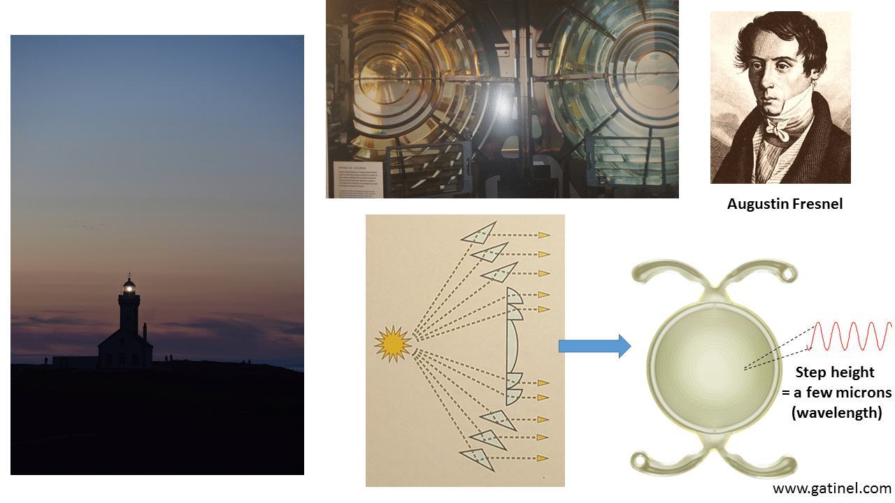
Light house at « Les Poulains », Belle-Ile, French Brittany (Bretagne). In 1821, Augustin Jean Fresnel introduced the lens for improving the visibility of lighthouses.
This French army engineer made a lens where some parallel blocks of glass were removed . Over and under the central glass drum, this created curved dioptic prisms. Above those were curved « catadioptic » prisms(partly reflecting light) that bent the light horizontally.
The lens was not made for imaging, hence its optical quality was not the priority in its design. It was capable of collecting most ot the lamp’s light to focus it toward the horizon. Diffractive IOLs are not directly inspired from the lighthouse lamps, but derive from the work of Fresnel and others in the field of diffractive optics. The geometrical similarity between the bulls’eye and the diffractive steps stems from the diffractive design requirements (basically, the height of the diffractive steps of the IOl are of about the same dimensions of multiples and fractions of the visible light wavelenghts).
The profile of a multifocal diffractive IOL derives from the Fresnel zone plate.
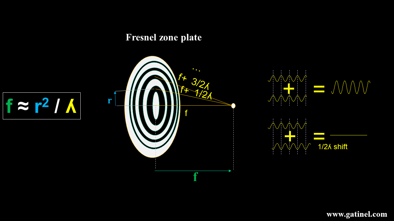
A semi transparent plate in air can create a relative increase of light energy a specific distances along the optical axis for a specific wavelength ʎ . To achieve this, one can block specific zones, where the optical path (here in air) from the zones to the desired focal distance f is equal to the distance to f along the optical axis, plus an even number of half wavelengths. Less negative intereference results in a relative increase of light energy at f. Diffractive IOLs do not block light, but the diffractive zones which constitute what is calle a « kinoform » (repetitive variation of the lens thickness) allow to selectively delay the incoming light waves (shift their phase) so that they interfere again constructively at the desired focal distance. The shorter the wavelength, the longer the focal distance. The shorter the focal distance, the smaller the diameter of the zones radii.
Zone plates are not efficient, mainly because they block part of the incident light. By using Fermat’s principle, progressive modifications to the zone plate can be made to obtain higher efficiency and decrease the number of foci. The plate can be made transparent, and the blocking zone replaced by « phase shifting » zones which selectively modify the optical path to cancel the half wavelength phase shifts and make more light interfere constructively to the desired focal distance. These zones look like little grooves, which can be made using microlithographic techniques on transparent lens materials.
Before going further, it is important to expose a little bit of theory and remind some of the important properties of diffractive IOLs. To understand how to achieve clinically efficient trifocality, it is mandatory to know the basic principles of diffraction for the realization of bifocal optics. At this stage, it is mandatory to realize that diffractive elements are very sensitive to the wavelength.
Basics of a bifocal diffractive IOL
Bifocality can be achieved by the combination of a conventional monofocal optic, and a “kinoform zone plate”, which profile results of the application of the Fermat’s principle (which states that light will always take the shortest path in time between two points). In gross approximation, the profile of the kinoform ressembles that of an asymetric “saw-tooth” profile. In practice, the height of these steps is of the dimensions of a few microns. This is somewhat expected, as this scale is of the same order than that of the wavelength of the incoming light (the visible light average wavelength is close to half of a micron, i.e 500 nanometers).
Mathematical design
(This section can be skipped for the non specialist)
The phase shift created by a diffractive surface is proportional to the height h(r) of the surface profile and the wavelength of light λ. The equation governing the phase shift φ(r) at a radial distance r from the optical axis is given by:
φ(r) = 2π h(r) (n2 – n1)⁄λ
Where:
- h(r) is the height of the lens surface at radius r,
- n1 and n2 are the refractive indices of the surrounding medium and the IOL material, respectively,
- λ is the wavelength of light, typically 550 nm.
This equation forms the foundation for designing the diffractive profiles used in the FineVision IOL.
Kinoform profile
The FineVision IOL leverages kinoform profiles, which are diffractive surfaces with continuous phase modulation. Kinoform profiles are designed to reduce the energy lost to higher diffraction orders, making them more efficient than traditional diffractive surfaces.
The general equation for the height profile H(r) of a kinoform diffractive lens, as described in the patent WO2011092169A1, is:
H(r) = a(1 – r3⁄R3)λ⁄2π(n2 – n1) mod[(F – √(r2 + F2)) 2π⁄λ, 2π] + π
Where:
- a is the amplitude parameter specific to the lens design,
- R is the radial distance from the optical axis to the edge of the lens,
- λ is the wavelength of light,
- n1 and n2 are the refractive indices,
- F is the focal length associated with the diffractive order.
This equation looks rather complicated but explains the classic « saw tooth » aspect of diffractive IOLs.
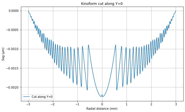
Representation of the diffractive kinoform profile, with apodization (note the progressive reduction of the height of the steps away from the center of the IOL)
The FineVision IOL combines multiple such diffractive profiles to create a trifocal effect, balancing light between near, intermediate, and far distances.
Optical Design of the FineVision Trifocal IOL
Calculating Focal Lengths
In the FineVision IOL, the diffractive structure is designed to focus light at three distinct focal points: near, intermediate, and far. The focal lengths for near and intermediate vision are determined by the following vergence formula:
F = n1⁄P
Where:
- P is the lens power in diopters,
- n1 is the refractive index of the surrounding medium.
For a near vision power of +3.50D and an intermediate power of +1.75D, the focal lengths are calculated as follows:
F1 = 1.334⁄3.50 ≈ 0.3811 m
F2 = 1.334⁄1.75 ≈ 0.7623 m
These focal lengths are used to design the diffractive profiles H1(r) and H2(r), which manage the light distribution to the near and intermediate foci, respectively.
Mathematical Formulation of Diffractive Profiles
The FineVision patent describes the height profiles for the near and intermediate foci using the following equations:
First diffractive profile for near vision:
H1(r) = a1(1 – r3⁄R3)λ⁄2π(n2 – n1) mod[(F1 – √(r2 + F12)) 2π⁄λ, 2π] + π
This profile focuses light for near vision, corresponding to approximately 300 mm (+3.50D).
Second diffractive profile for intermediate vision:
H2(r) = a2(1 – r3⁄R3)λ⁄2π(n2 – n1) mod[(F2 – √(r2 + F22)) 2π⁄λ, 2π] + π
This profile manages intermediate vision, focusing light at approximately 600 mm (+1.75D). Both profiles are superimposed onto the lens surface to create the trifocal functionality.
Optimizing Light Distribution
The FineVision lens is designed to distribute light efficiently among the three focal points, allocating roughly 42% of light to far vision, 36% to near vision, and 22% to intermediate vision. This allocation ensures that patients can function across a wide range of activities without the need for additional corrective lenses.
In addition to optimizing light distribution, the FineVision design also addresses chromatic aberrations by adjusting the height of the diffractive zones. This reduces chromatic aberration in varying lighting conditions, enhancing the clarity of vision at all distances.
General Properties of kinoform for bifocal IOLs
Here we will return to a simpler and more visual approach. The following illustration represents schematically the behavior of light waves diffracted through a kinoform.

The focal distance of the kinoform is a function of the width of the steps. The diffractive properties of the kinoform pattern are mainly governed by the height of the steps. The height of the steps can be made constant; for a specific incident light wavelength (ex : 550 nm), it would result in a constant ratio of split between a proportion of « 0th order diffracted » light waves(for which all happens as if there is no kinoform) and the « 1st order diffracted » light waves, which will bent toward the optical axis of the lens (for clarity reason, the illustration shows the « left half » of the incident light split). In this example, 40% of the 100% incident light energy is not deviated, 40% is deviated (1st order), and 20% (not shown) are diffracted in higher orders. This split happens when the height of the steps is adjusted to be close to half of the wavelength of the considered light wave in the kinoform material. Conversely the height of the steps is equal to the optical path of one wavelength, most of the light energy will be concentrated to the 1st order of diffraction.
When properly designed, the kinoform can split incident light into several foci. This will happen when the optical path represented by the height of the steps is not equal to an even number of the considered wavelength in the lens material. Some percentage of the incident light may also not be deviated by the kinoform (0th order), while some other percentage might be to to the near foci (1st order) . Some calculation shows that some other remaining percentage of the incident light energy (20%) is diffracted in other orders than the 0th (non deviated) and the 1st (near foci) when the kinoform is designed to be « bifocal » for a specific wavelength.
Effects of the width of the diffraction steps:
The width of the steps governs the distance to where the 1st (and subsequent) orders will come into focus.

The width between each kinoform step controls the amount of added vergence: from the center to the periphery of the kinoform, the space between each step tends to decrease (as shown by the double yellow arrows). If the steps all had the same width, the light energy diffracted in the 1st order would be deviated to another direction in a « parallel » fashion instead of converging to distinct foci. The higher the addition (the shorter the distance to 1st order foci), the coarser the rings are, globally. Reciprocally, enlarging the spacing between the steps results in a lesser added vergence. Hence, one could think of enlarging the steps from a +3D design until an addition of +1.75 D of vergence is provided. The AMO Symfony lens has an « echelette » structure, which may be a more attractive name for « kinorm steps » or « diffraction grating », which number corresponds to an addition power of +1.50 D – with respect to the nominal distance power of the IOL. However, the height of the steps of the AMO Symfony is larger than the Tecnis bifocal IOL, to provide some of the chromatic compensation by diffracting most of the light into the 1st (distance) and 2nd (intermediate) orders of diffraction (and leaving the 0th order with no energy).
Apodization : reducing the height of the diffractive steps of the IOL
The height of the steps is controlled by the value of the considered design wavelength: optical designers may choose 550 nm, as it is the wavelength to which foveal (precise) vision is the most sensitive to. If the steps have a constant height value throughout the IOL, the repartition of the incident light energy between the various diffraction orders will also be constant. A progressive reduction of the height of the steps can be achieved to modulate the repartition of the incoming light energy into the different diffraction orders with the pupil diameter. This reduction is called « apodization ».
Vergence of higher diffractive orders
It has been mentioned previously that the kinoform diffracted light into several orders beyond the 0th and the 1st order; these represent 20% of the initial light energy, provided 40% is diffracted toward the 1st order, and another 40% is diffracted (but not optically deviated) toward the 0th order. The 0th order contributes to distance vision, the first order contributes to near vision, and the second and superior orders are lost for vision, as their vergences (the distance of the foci) are not useful.

As noted previously, 20% of the incident energy is lost, because it is « dispersed » in other diffraction orders by the kinoform.
Interestingly, with such a design, the second diffractive order has a double vergence that of the first order.

One interesting properties of kinoforms relates to the relation between the diffraction orders and their respective vergences. The light energy directed to the 2nd order of diffraction has a vergence doubled to that of the 1st order (the focal distance is half of that of the 1st order); hence, for a 3.50 D 1st order vergence, the 2nd order will have a 7D vergence. Thereis an harmonic relation between diffraction orders foci, and their respective vergences.
Achieving trifocality
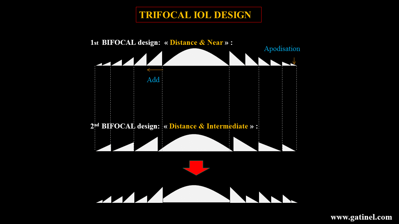
The combination of two specific diffractive kinoform patterns makes the envisioned asymmetric distribution of light energy among the 3 foci possible.

The core of the trifocal design is based on the combination of two diffractive profiles: one intending to provide +3.50 D of added vergence, the other one to provide +1.75 D of added vergence (this amount corresponds to what is needed for the intermediate vision). One must realize here that the 2nd order of diffraction of the bifocal design (« distance and intermediate ») has a vergence equal to the double of the 1st order : 2 x 1.75 D = 3.50 D. This 2nd order is not « lost » for the patient, as it will contribute to the near vision foci ! nb : On this diagram, the diffractive profiles are not apodized.
The final Finevision trifocal IOL profile (patented) is a combination of two apodized profiles. It displays a full diffractive area with a specific diffractive pattern comprising alternating diffractive steps of different heights.
The FIneVsion IOL design is depicted schematically : the harmonic relations between the two combined bifocal diffractive designs allow the diffractive steps to nicely combine, and alternate regularly. The height of theses steps is adjusted to provide the appropriate amounts of energy toward the distance, intermediate, and near foci.
This diffractive area extends throughout the anterior side of the IOL. The zeroth (0th) order of the two profiles is used for far vision.

The patented design of the Finevision trifocal IOL (Physiol) is based on the combination of two bifocal diffractive patterns (« bi-bi » profile). Compared to conventional bifocal IOLs, there is less loss of « useful » light energy, since the light energy diffracted in the 2nd order by the « IOL n°2 » gets reintegrated for useful near vision!
In this innovative trifocal IOL design, the first kinoform pattern is designed with an addition of 3.5 D as the first diffraction order. Therefore, the second diffraction order occurs at a vergence of 7D, which corresponds to lost light for useful vision. In contrary, the second kinoform pattern’s first order provides an addition of 1.75 D (intermediate distance); hence, the second order has a vergence of 2X1.75 = 3.50 D.
Therefore, the 2nd order of the second diffractive pattern is used to reinforce approximately 5 % of near vision (Add +3.5D), which is mainly afforded by the first order of the first diffractive pattern. As a result, the percentage of lost energy, which is usually 20% for standard diffractive bifocal lenses, is reduced with this IOL to approximately 14 %. The relative gain in terms of saved energy is approximately 25 % when compared with standard diffractive IOLs.
The IOL diffractive profile is also gradually attenuated throughout the entire optic (apodization), resulting in a continuous modulation of the light energy distribution directed to the three primary foci. The larger the considered zone, the more light is proportionally directed to the distance foci.

This diagram depicts the respective apodized profile of the Finevision trifocal IOL (bottom). The apodization reduces the steps height. Note that the difference in spacing of each combined profile results in a more complex pattern. The difference in the respective steps heights is dictated by the need for an optimal light energy balance between distance, near, and intermediate foci.
This profile is lathed on the surface of a monofocal apsherical optic. The asphericity of the monofocal lens is intendend to optimize the image quality, by balancing physiological levels of the corneal positive spherical aberration.
Apodization of the trifocal profile
As the step height decreases towards the periphery (apodization), when the pupil aperture becomes larger, the peripheral steps are progressively exposed. This results in an increasing amount of light dedicated to the distance vision foci. Hence, less light is recruited for the near and intermediate focal points. This gradual decrease of the step height from center to periphery has been shown to reduce halos, which are generated by defocused light under dim conditions. In contrary to non-apodized IOLs, the apodization provides some degree of customization to pupil movements: near reading tasks trigger pupil constriction, while mesopic distance vision (eg night driving) incurs pupil dilation. Apodization allows more light to be directed into the distance foci (0th order) when the pupil is dilated and uncovers a larger IOL surface. This warrants superior optical performance in mesopic conditions.
Convolution of the trifocal profile
Diffraction can occur when light waves encounter any « abrupt » change in their path. The sharp edges of each of the steps can cause unwanted diffraction, causing a slight dispersion of incoming light energy. The light scattering on the edges of the steps can be decreased by their smoothing. Theoretically this can be simulated by adding a mathematical smoothing function, called “convolution”. This function was optimized to fit the lens profile as manufactured, according to the geometry of the cutting tool, as in practice, it is not possible to achieve abrupt steps with current lathing technology.
Optical bench results of the Finevision trifocal IOL
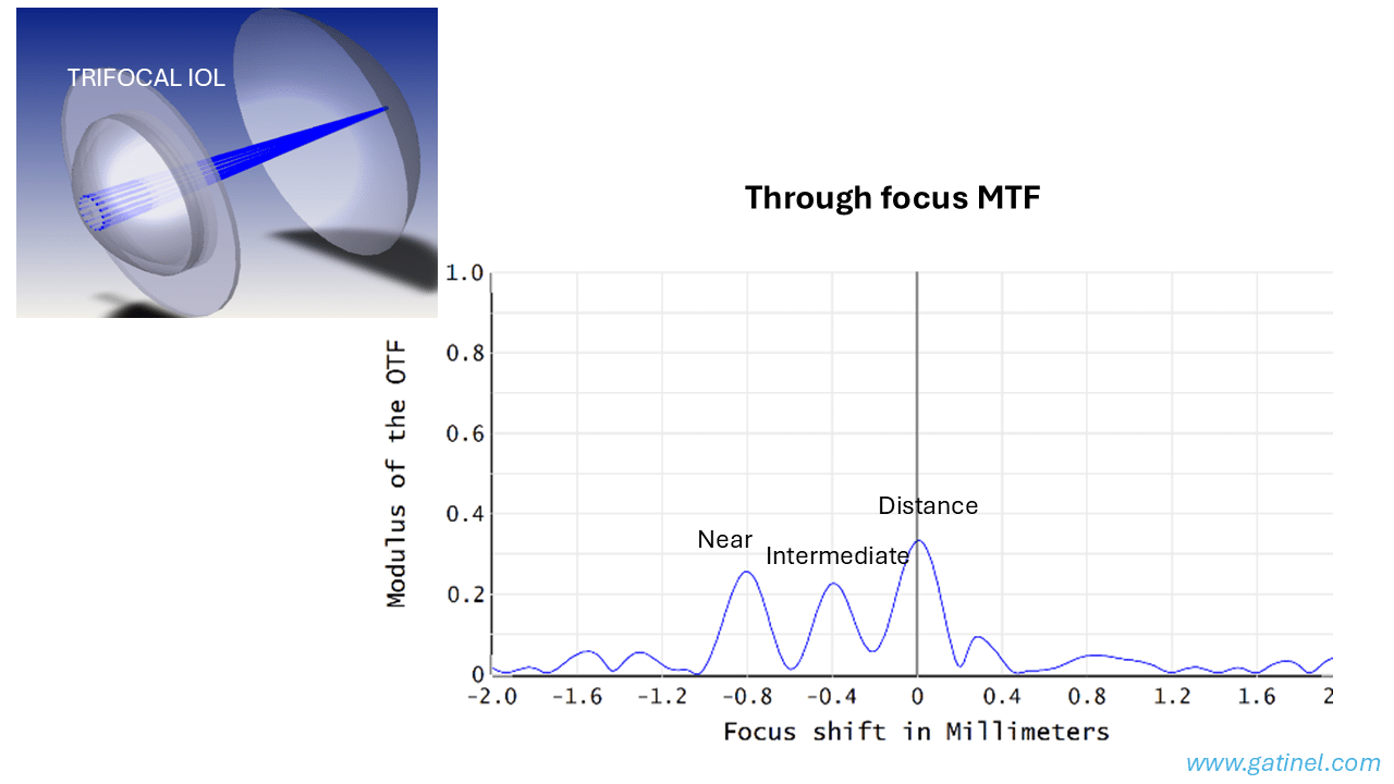
The optical bench evaluation (through-focus and through-frequency MTF) has been carried out according to ISO quality standards. These optical bench results echo the theoretical results. In addition to the two major foci at 0 and +3.5 D add power for far and near vision, respectively, the Fine Vision multifocal IOL displays a focus at +1.75 D, which corresponds to intermediate vision. This characteristic should, therefore, offer enhanced visual performance for intermediate vision relative to that obtained by conventional bifocal multifocal IOLs.

This through focus MTF curves, obtained in a artificial eye implanted with the Finevision IOL demonstrates the existence of a true intermediate foci, and the variation of the light energy repartition with different apertures.
The diffractive profile test has been designed to extend throughout the entire optical surface of the Finevision trifocal IOL. The gradual decrease in step height towards the periphery allows to reinforce the distance vision under mesopic conditions, in which the human eye’s pupils dilate. Without this gradual reduction, the contribution to far, intermediate, and near vision would be constant across the entire optical surface for any pupil size: this would not be optimal as all human pupils tend to dilate when ambient light reduces and to constrict when attempting to perform near visual tasks such as reading. The variations of the through-focus MTF curve of the IOL for different pupil apertures confirm that the Fine Vision IOL is pupil-dependent and designed to favor distance vision under dim light conditions. This change of energy balance with pupil size mimics the natural pupil’s response to various lighting conditions. It is a function of the required distance (near or far vision). It is consistent with the accommodation reflex, in which the pupil tends to constrict for near vision.8 To decrease the risk of glare at night, only 9 % of the energy is devoted to intermediate vision at a 4.5-mm pupil aperture.
The Finevision Physiol trifocal IOL was the first IOL ever designed to display a useful additional focus for intermediate vision at +1.75 D. This IOL improves intermediate vision relative to standard bifocal IOLs, while maintaining near and far visual performance owing to its advanced optical features: apodization, convolution, aspherization.
The risk (for the patient) associated with this intermediate focus seems limited with respect to the offered benefit because the diffractive structure of this trifocal IOL was designed to allocate less energy to intermediate vision as compared to far and near vision. Regardless of the pupil size, the limited amount of energy allocated to intermediate vision minimizes the risk of monocular diplopia associated with intermediate focus.
Here is a through-focus MTF curve obtained in a model eye (Arizona) for a 2.6 mm pupil:
Ray-traced based through focus MTF (Zemax) – trifocal IOL
Hello Dr Gatinel. I am a South Korean opthalomolgist who is a big fan of your works.
Starting from this page, I have tried to understand the mathematical principles behind diffractive bifocal IOLs. However, combining two bifocal diffractive designs to achieve trifocality remains still elusive to me.
Specifically, in the above image titled « TRIFOCAL IOL DESIGN, » the lower trifocal design, if we ignore apodization, appears similar to a bifocal design. In this design, each triangle seems to have the same width corresponding to +3.5D. The only difference is the alternating heights, controlling the light distribution.
As shown in the image, if the initially wider triangle for +1.75D is cut in half and the base half is removed to incorporate the narrower +3.5D triangle, how can the remaining apex half still function to provide a +1.75D power with only half the original width?
Thank you.
Thanks, it appears to me that Kappa angle and pupil size do not really affect the performance of trifocal IOLs. It is important to perform an uneventful surgery, and control for astigmatism. If the cornea is irregular (trefoil and coma like aberration), the indication can be reconsidered. But otherwise the precautions and recommendations of these IOLs are the usual ones when it deals with cataract surgery and premimum multifocal implantation.
Congratulations Dr. Gatinel on a very comprehensive and detailed presentation. I was wondering if you could comment on your recommendations for pupil size, Coma, Angle Kappa and any other parameters that you feel are necessary to consider in chosing the pts. for this trifocal IOL.
Thank you,