Spiral Optics and Dioptres: Presentation and Explanations
Spiral Optic and Dioptre in Ophthalmology
The recent introduction of a new multifocal lens, known as the « spiral » lens (Galaxy, Rayner), has garnered significant interest. This page is dedicated to an illustrated description of related technology, which aims to impart multifocal properties to an extraocular optic (contact lens) or intraocular optic (intraocular lens: IOL). The information contained on this page does not originate from any medical laboratory or company providing artificial lens implants. In particular, it does not come from Rayner, the company that recently launched the Galaxy lens. However, it is likely that there are similarities and functional analogies with this so-called spiral lens, described as having « additional refractive power variation inserted along spiral tracks » (see related patent).
Introduction
The literature on spiral optics is relatively sparse. A patent related to a « spiral diopter with meridians of different powers » appeared in 2023, providing detailed information on the equations that describe the key characteristics of spiral technology. The patent authors have applied their innovation to a contact lens. To date and my best knowledge, no clinical data has been published on the in vivo performance of these devices.
Generalities
We intuitively understand a spiral curve: it describes a shape characterized by progressive distancing from a central point. Spirals, of which there are several types, play a fundamental role in various fields of mathematics, physics, biology, and engineering. Spirals can be found in natural patterns, such as the arrangement of leaves on plants or the spirals of snail shells. This type of spiral is related to the golden ratio and can be approximated by a logarithmic spiral based on squares whose sides are Fibonacci numbers. The hyperbolic spiral is another type of spiral characterized by infinite coiling at its center.
The Archimedean spiral is a basic spiral where the spacing between the coils is constant. It is the path traced by a point moving uniformly along a line that is itself rotating uniformly around a fixed point. The groove on a vinyl record is an example of an Archimedean spiral.
Its curve is defined by the following polar equation: ρ = bθ. Here, θ represents the angle in radians (ranging from 0 to infinity, passing through π, 2π, 3π, etc.). ρ is the radius (the distance from the origin to the point on the spiral). b is a constant that controls the spacing between the arms of the spiral.
Let us suppose that b = 0.5 (this controls how tightly the spiral winds). Now, for different values of θ: when θ = π(180 degrees): r = 0.5(π) ≈ 0.5(3.14) = 1.57. The point is at an angle of 180° is at a distance of approximately 1.57 units to the left of the origin.

Representation of two Archimedean spirals (a=1/Pi vs. a = 1.0). Left : the distance to the center of the spiral is r=1 when the angle theta is Pi). Right: the distance to the center is equal to the value of theta in radians.
Analytical description of a spiral diopter
The analytical description of the equation used by Galinier et al. is significantly more complex:
𝐶 = 2𝑐1 (1 + cos(Nϕ + ηρ(r)^2)) + 2𝑐2 (1 – cos(Nϕ + ηρ(r)^2))
Let’s take a closer look at the mathematical structure of this function.
Basic Parameters and Variables:
- c1 and c2: constant coefficients that influence the amplitudes of the components of the function C.
- N: number of complete turns of the spiral. It controls the angular frequency in the function cos.
- η (eta): parameter that controls the influence of ρ(r) in the cosine argument (its the topological charge, related to the number of spires around the central axis)
- r: radius of the spiral.
- R: The maximum radius of the spiral (half the given diameter).
- ρ(r) = r / R: A function normalizing the radius relative to the maximum radius.
Structure of the function C:
The function C is composed of two main terms, each multiplied by a constant (c1 and c2).
Each term contains a cosine with a complex argument.
Details of the Terms:
- First term: c1 (1 + cos(Nφ + ηρ(r)^2))
- Second term: c2 (1 – cos(Nφ + ηρ(r)^2))
Mathematical Interpretation:
-Cosine Superposition: The function C is a linear combination of two oscillatory terms. Each term is a cosine shifted in different ways, with amplitudes modulated by c1 and c2. Angular and Radial -Modulation: The cosine argument combines an angular part (Nφ) and a radial part (ηρ(r)2). This means that the shape of the spiral depends both on the angle and the radial distance.
-Effect of ηρ(r)2: The addition of(ηρ(r)2 into the cosine argument introduces a distortion depending on the radial distance to the fourth degree. This distortion becomes more pronounced as r increases, adding nonlinear features to the spiral.
Visualization of a Spiral Diopter
The mathematical structure of C produces a complex surface with undulations influenced by the parameters c1, c2, N, and η. By adjusting these parameters, different shapes of spiral surfaces can be obtained.
-Variation of the amplitude of the coefficients:
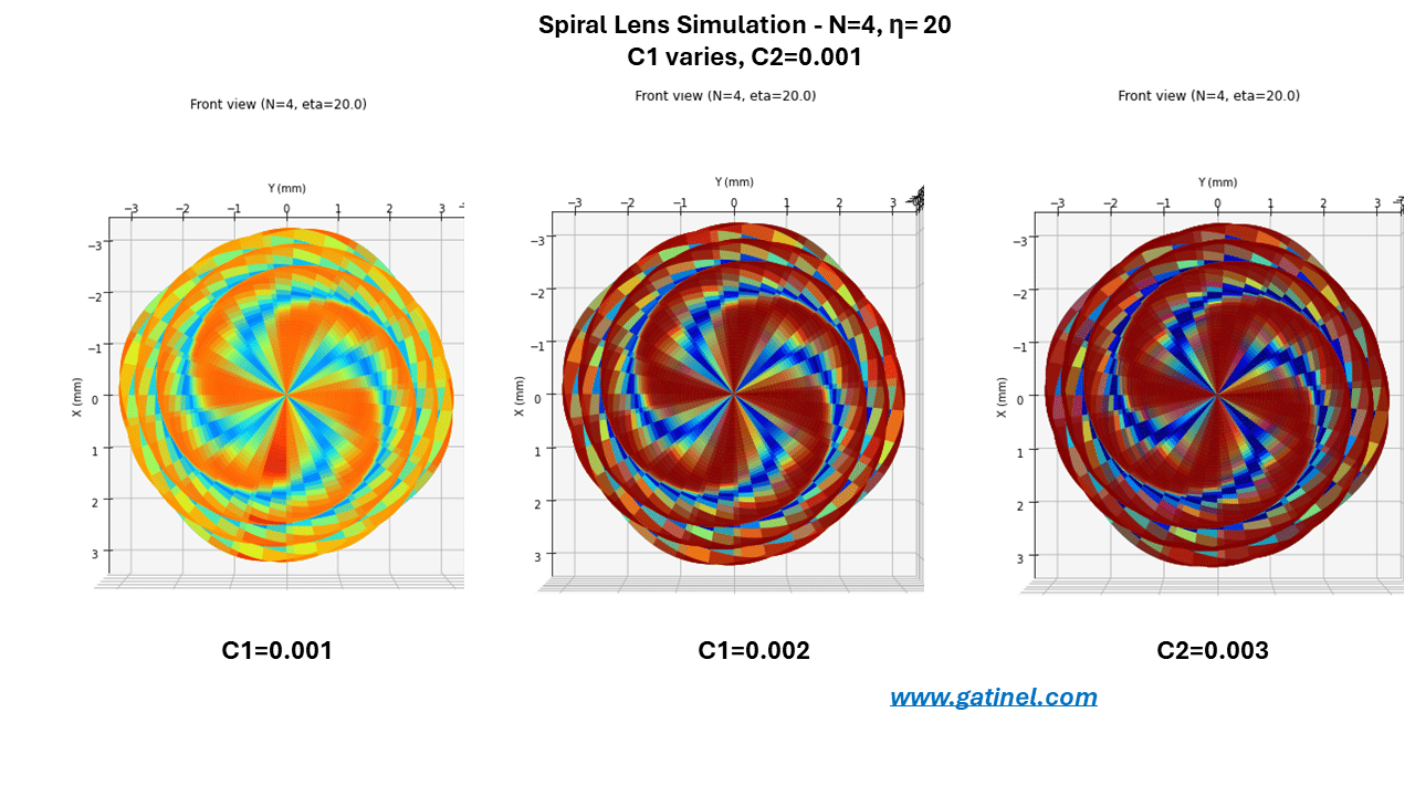
Impact of the coefficient on the amplitude of the spiral pattern
-Variation of N (number of spiral branches):
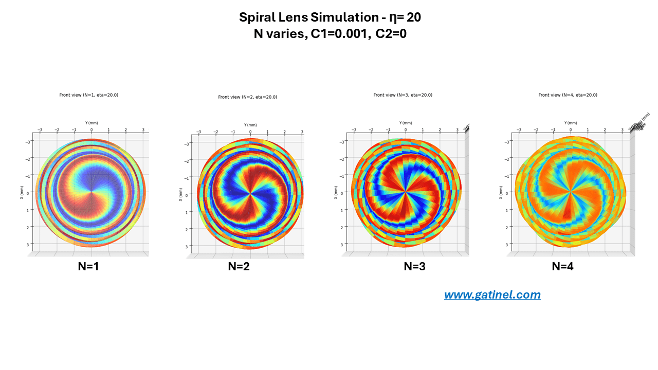
Impact of N (number of branches)
Impact of η (eta) – degree of spiralization:

Impact of eta on the spiral shape (degree of spiralization)
Optical Impact of Spiral Refractive Structures (simulations)
The principle involved here considers the main focal lengths of a toric lens (N=2, η= 0 !), which can be thought of as defining a range where a certain depth of field exists.
The spiralization of the diopter (its twist along the optical axis, that occurs by altering the value of η) allows for modifying the distribution of light intensity while maintaining a distribution that is predominantly between the main focal points.
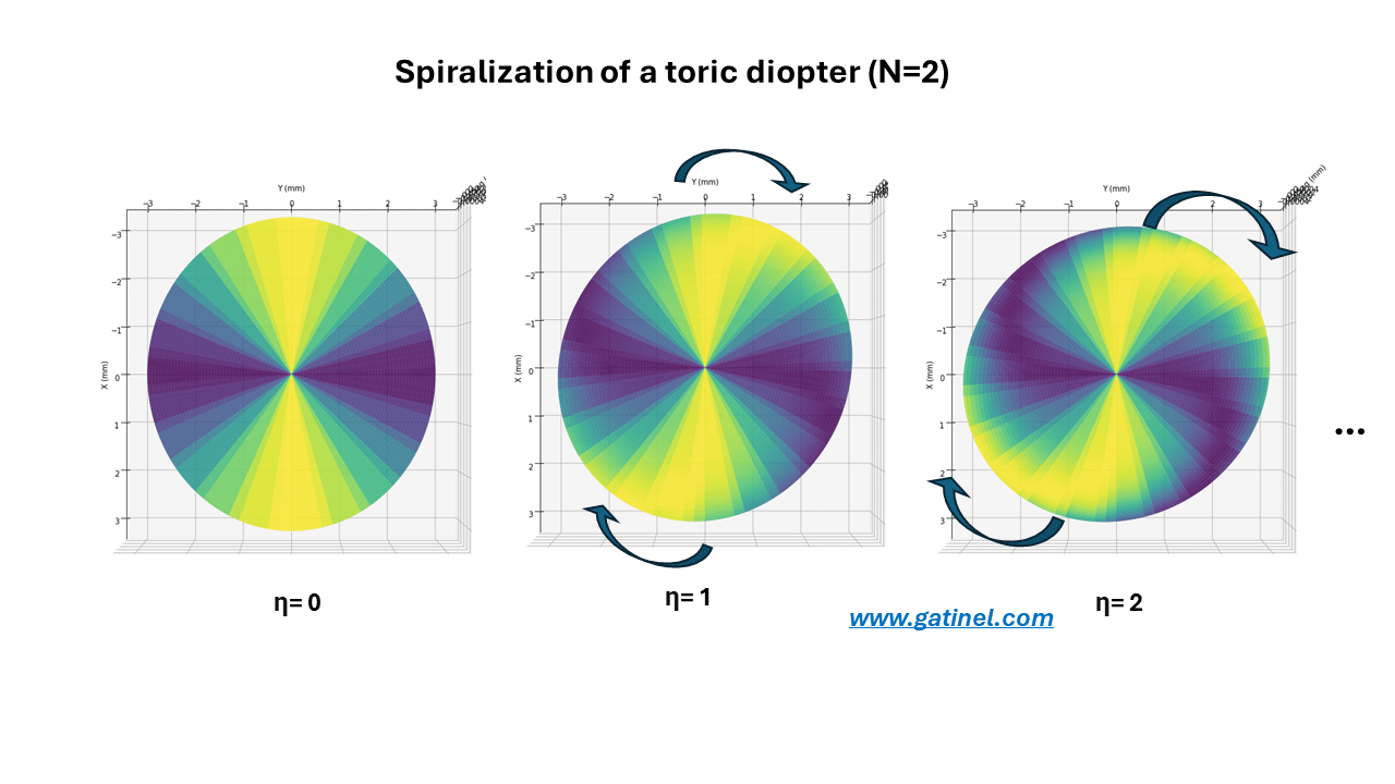
Spiralization of toric diopter (N=2)
We can consider an intraocular lens (IOL) with a surface equipped with two principal meridians of different power (but now arranged in an alternate of four spiral branches: N=4) and « twist » it around the optical axis. This results in a geometry that conforms to some of the representations above for N=4. It is hoped that this deformation will preserve, yet enhance, the optical quality of the main focal points, and therefore extend the depth of focus of the IOL.
In the following, the spiral refractive lens is modeled using the equation of C, but with a variable corresponding to elevation (sag) information rather than curvature. This allows simulations to be carried out with the Zemax (Ansys) software. These theoretical simulations still provide insights into how a toric and spiral surface refracts incident light rays.
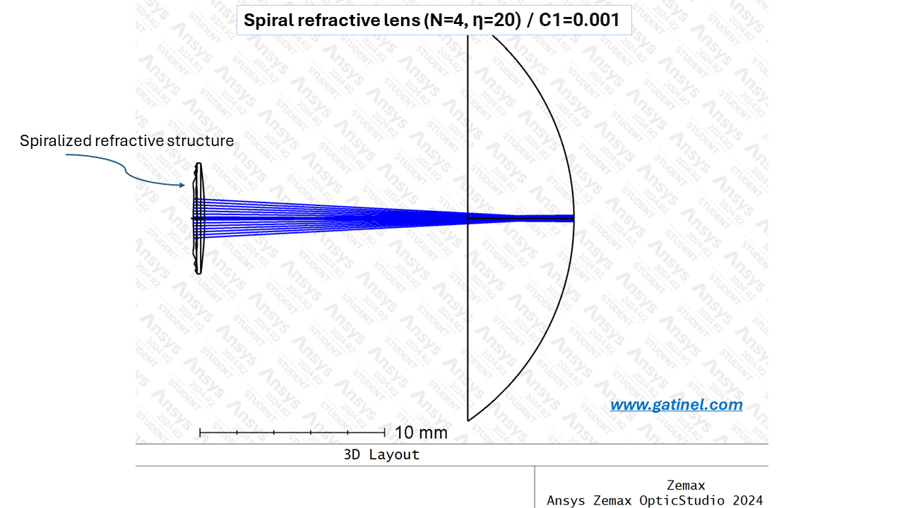
Side representation of the ray path (cornea not shown) through the spiralized IOL.
This allows for the study of optical properties in terms of through-focus MTF, convolved images, and through-focus ray spot diagrams (Arizona Eye Model, aperture stop diameter: 5 mm)
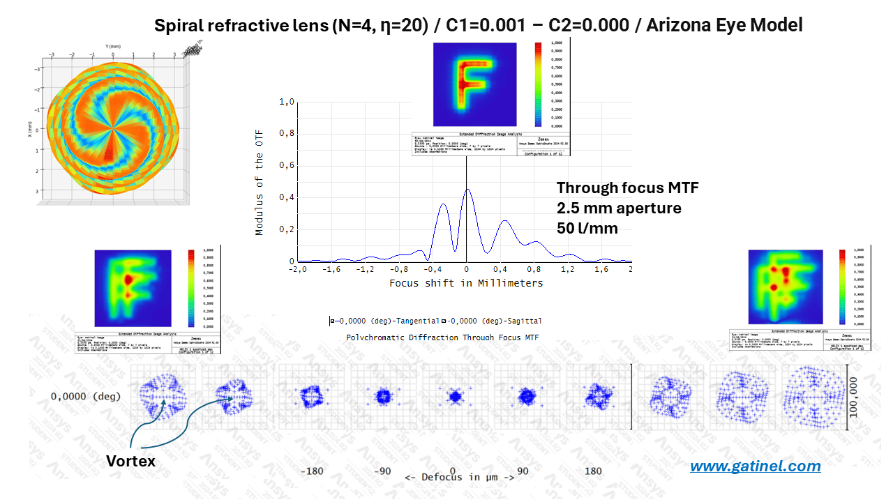
Optical quality metrics and properties of a modeled IOL with spiral refractive geometry.
We observe the presence of three peaks on the through-focus MTF (an additional peak in front and another behind) the focal point associated with the monofocal carrier optic. The genesis of these peaks is induced by the peripheral « wrapping » of rays due to the spiralization. This causes a relative deficit in light intensity at the center of the refracted beam (vortex). The focal point of the optic without the spiral refractive pattern becomes an intermediate focus when the spiral refractive pattern is added (whereas it would be the distance focus with most diffractive trifocal IOLs). Here, the principle is different because, unlike a diffractive lens that produces positive-order foci (where the vergence adds to that of the lens, ex: +1.75D and +3.50 D), the wrapping of the rays (vortex effect) shortens and extends the focal depth on either side of the main optical focus of the monofocal « carrier » lens (ex: -1.50D and +1.50 D).
As a consequence of this particular vortex geometry, the convolution of images for focal points outside the focal zone shows « ghost » replicas, which are linked to the particular grouping of certain ray bundles.
To illustrate the genesis of extended focal distance and explain the presence of the three main peaks in the through-focus MTF, one can simulate the ray paths through a spiralized optic with high coefficients (c1=0.1). In this simulation, the rays appear to form three zones that are particularly concentrated within the focal region (red arrows).
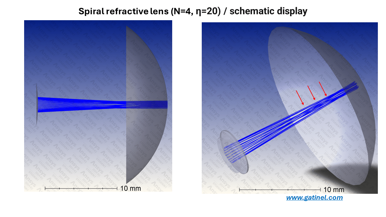
Schematic representation of the ray paths through a spiral IOL (cornea not shown): the specific wrapping generated by the spiral refractive structure is responsible for three particularly dense zones of rays.